MENU
BUY PARTS
REQUEST QUOTE
FIND LOCATION
back
to top
Back to listing page

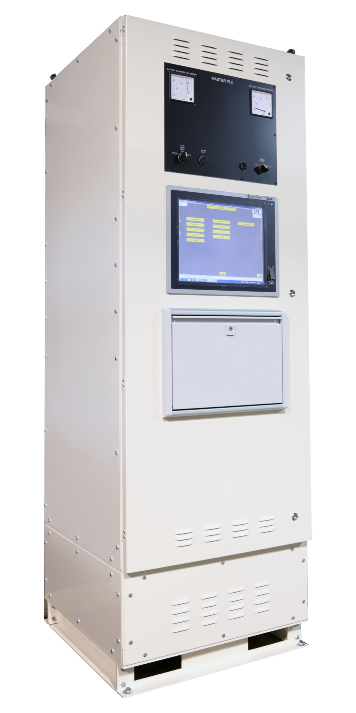
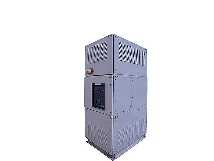
PLC and SCADA Control Systems

Switchgear and Paralleling Controls
Configuration IP4X
Operating Temperature 0 - 50 °C (32 - 122 °F)
Dimensions Depth 750 mm, Width 750 mm, Height 2200 mm
Application LV and MV

Availability Please Call Admin

OVERVIEW

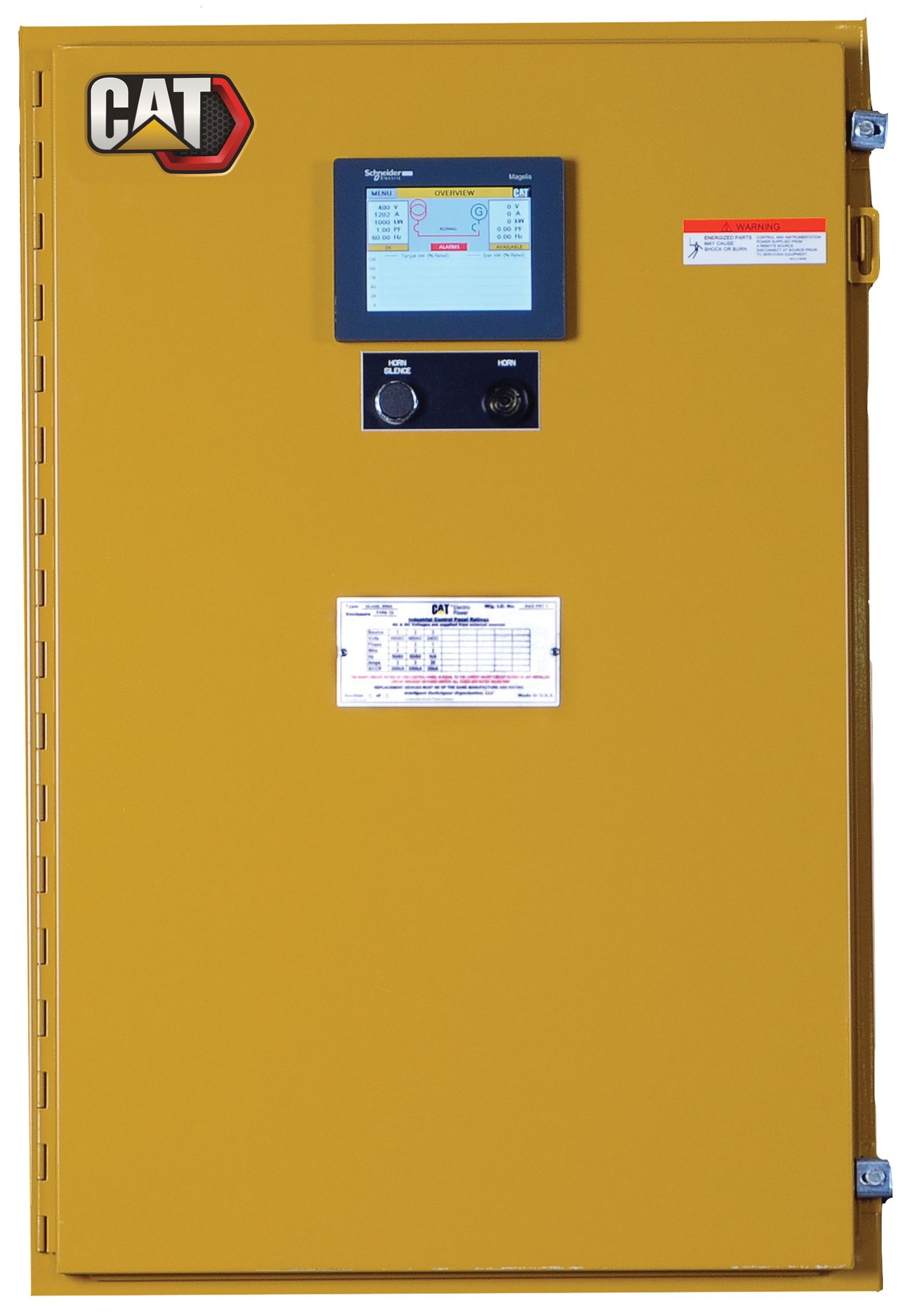
Various applications are available such as Multiple Generator Control, Multiple Utility control (including Peak Lopping/Shaving), Load Management control and Balance of Plant control. At a basic level, a Master PLC panel is wired in conjunction with the generator control panels and associated switchgear in the system to provide the control for the power network and the starting and stopping of the generators. For more complex systems, a communication network can be utilised to facilitate the transfer of data between the PLC and outstations from different locations. The network comprises physical connections between all intelligent devices (or nodes) arranged into a ring formation and operating on the EtherNet/IP protocol.

FEATURES & BENEFITS

PLC and SCADA Control Systems

Auto/Manual control of generators and load breakers     Generator monitoring screens (Voltage, Frequency, Amps, kW, kVA, kVAr) Engine monitoring screens (Oil pressure, E... Read more

SPECIFICATIONS FOR PLC and SCADA Control Systems

Collapse All
Enclosure Rating
Configuration IP4X
Operating Temperature
Operating Temperature 0 - 50 °C (32 - 122 °F)
Dimensions
Dimensions Depth 750 mm, Width 750 mm, Height 2200 mm
Application
Application LV and MV
Modes of Operation
Modes of Operation AMF control, Multiple Generator control, Multiple Generator Group control, Multiple Utility control, Baseload control, Import/Export control, Load Management control, Balance of Plant control
Technical Summary
Technical Summary Customisable PLC and SCADA in a floor standing control panel.

SELECT MODELS TO COMPARE

Switchgear and Paralleling Controls

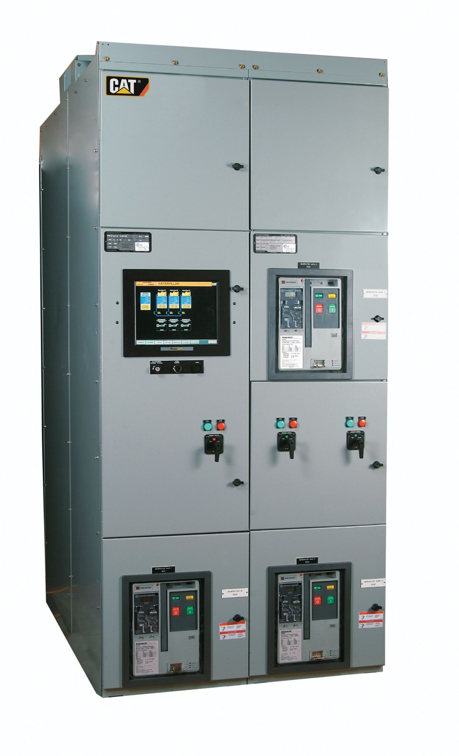
Engine Paralleling and Integration Control (EPIC)

Configuration Remote modular paralleling control system (Master Control Panel for the first 2 generator sets and optional tie breaker, separate add-on control panels for up to 8 additional generator sets, utility paralleling control, and distribution control)
Modes of Operation Emergency Standby with redundant master control, Utility paralleling, peak shaving, and closed transition to/from Generator Power (with optional utility control panel)
Application LV and MV (208V-27kV)
ANSI Protective Devices 15/25. 27/59, 81 O/U, 32, 40, 90 (Industrial Grade)
Switchgear and Paralleling Controls

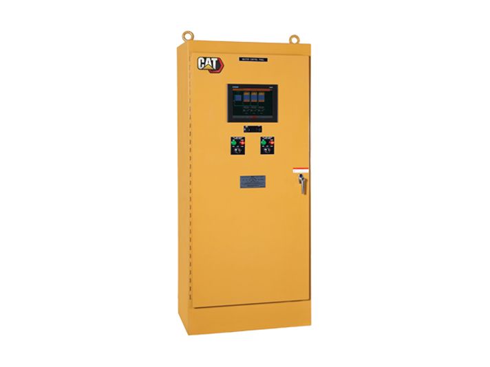
EMCP 4.4 Master Control Panel

Configuration Remote monitoring and control for up to 8 generator sets via high-speed network. Enables paralleling a group of EMCP 4.4 equipped generator sets to a single utility source.
Modes of Operation Emergency standby, island, utility paralleling
Application LV and MV (208V - 38 kV)
ANSI Protective Devices 15/25, 27/59, 81 O/U, 32, 40, 50, 51
Switchgear and Paralleling Controls

Cat Customizable Switchgear and Controls

Configuration Application-specific switchgear with control logic designed to meet any customer's sequence of operations. Examples are 3+ Utilities, CHP applications, complex load shed schemes, etc
Modes of Operation All modes of paralleling generator sets to each other and to other sources (utility, alternative fuels, wind, etc) can be supported. Caterpillar generation and control experts can design and program the most complex power schemes to meet your critical power needs
Application LV and MV ( 208V - 38 kV) 50 / 60 Hz
ANSI Protective Devices Per customer specification
Switchgear and Paralleling Controls

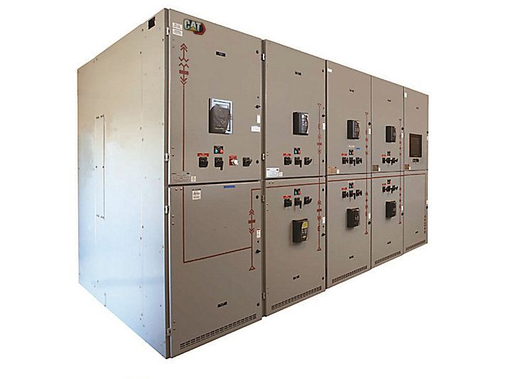
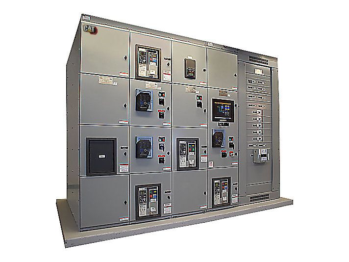
Cat Switchgear

Configuration IP4X
Operating Temperature 35 °C / 40 °C @ 1 hr, option for 0…50 °C (32…122 °F)
Standard Widths 600 mm for ABB Emax2 E2 1600 - 2500A. 750 mm for ABB Emax2 E4 3200 - 4000A. 1200 mm for ABB Emax2 E6 4000 - 6300A.
Technical Summary Modular system enables any configuration Distribution Boards, Motor Control Centers & PLC Control cabinets. Accommodates fixed or withdrawable breakers.
Switchgear and Paralleling Controls

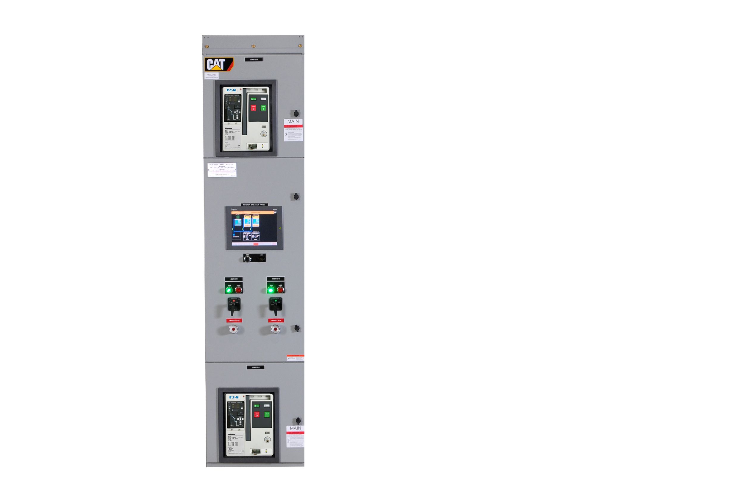
Engine Generator Integrated Switchgear (EGIS)

Configuration Floor Standing modular switchgear paralleling system (Master Breaker Panel for the first 2 gensets, separate structures for up to 8 additional gensets , utility, and load control/distribution)
Modes of Operation Emergency Standby with redundant master control. Utility paralleling, peak shaving, and closed transition to/from Generator Power (with optional utility control panel)
Application LV only (208V - 480V)
ANSI Protective Devices 15/25. 27/59, 81 O/U, 32, 40, 90 (Industrial Grade)
Switchgear and Paralleling Controls

Cat Microgrid master Controller (MMC-M)

Configuration Configurable PLC based switchgear capable of controlling and monitoring multiple generator sets, tie and load breakers in conjunction with downstream transfer switches for standby or emergency applications
Modes of Operation Multi-unit Island and multi-unit standby mode with optional redundant controls and components.
Application LV and MV (208V - 38 kV)
ANSI Protective Devices 15/25, 27/59, 81 O/U, 32, 40, 50, 51
Switchgear and Paralleling Controls

Cat XLM Switchgear

Configuration Configurable PLC based switchgear capable of controlling and monitoring multiple generator sets, tie, utility and load breakers for utility paralleling applications
Modes of Operation Emergency Standby, Utility Import/Export, Peak shaving, and base load operations with redundant controls and components. Closed transition to/from generator power
Application LV and MV ( 208V - 38 kV
ANSI Protective Devices 15/25, 27/59, 81 O/U, 32, 40, 50, 51
Switchgear and Paralleling Controls

Emergency Transfer Load Manager (EXL)

Configuration Wall mounted paralleling control system that monitors and controls a single generator and a single utility.
Modes of Operation Utility Import, Export, and base load operations, Peak shaving, and Emergency Standby. Closed Transition to/from Generator Power
Application LV and MV (208V-32kV)
ANSI Protective Devices 15/25. 27/59, 81 O/U, 32, 40, 50, 51
of

How to buy

VIEW ALL
01
SEND REQUEST

Select your equipment and fill out your contact information

02
GET A QUOTE

A sales rep will send you an official quote and other related information

03
PAYMENT & DELIVERY

Payment – Lead time - Delivery

Select Up to
3 Models to Compare
Model 1
Model 2
Model 3